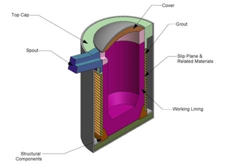
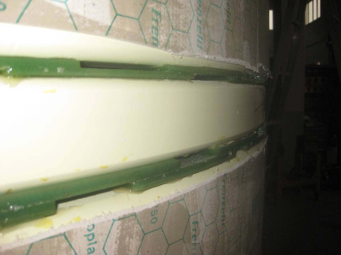
Profile of refractory

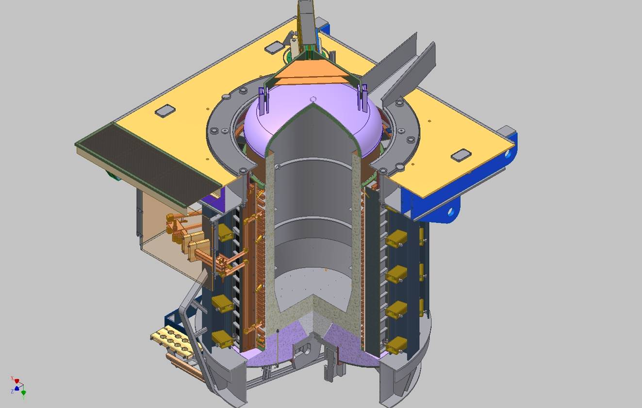
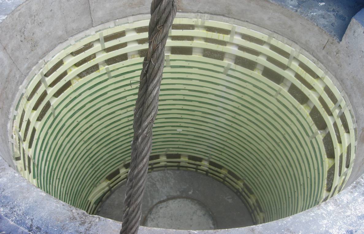
Profile of furnace


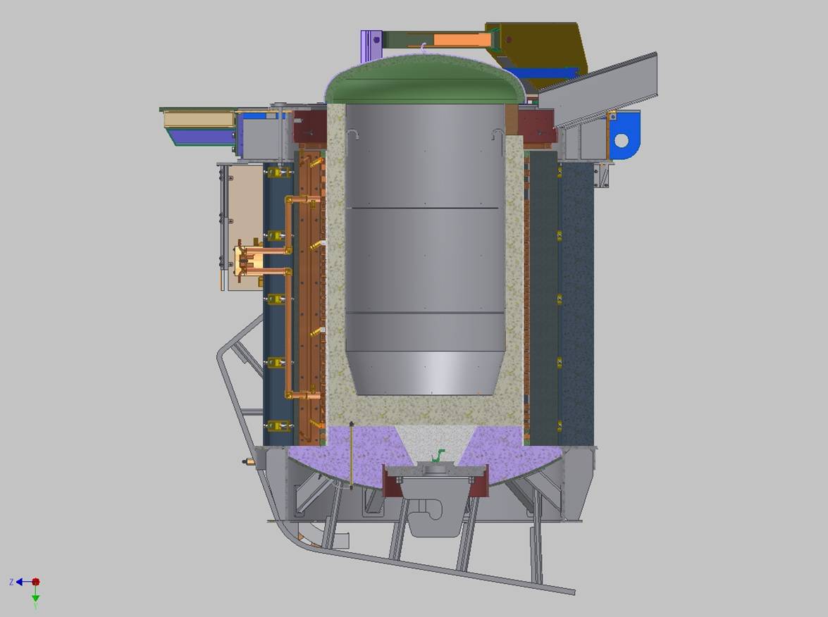
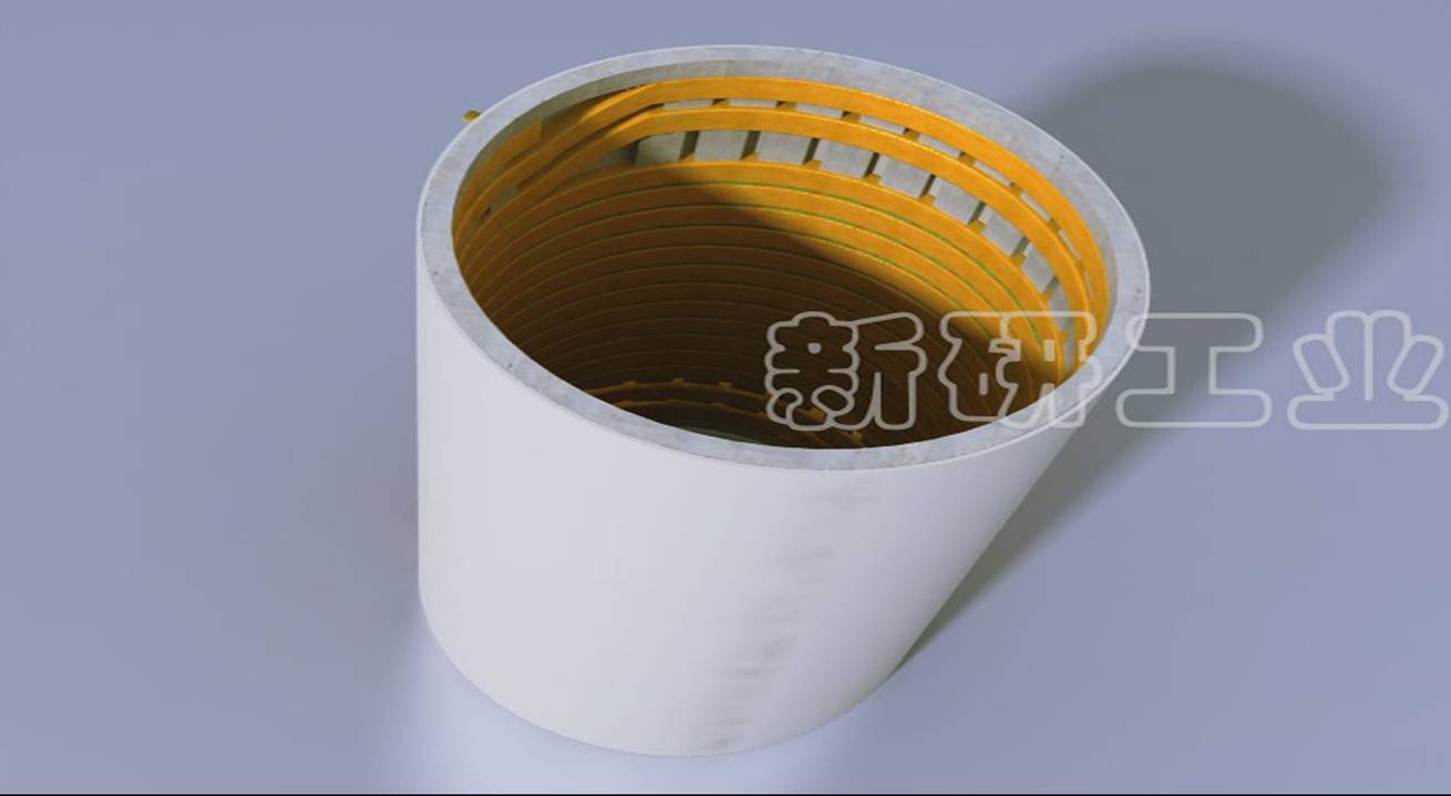
The relationship between coil and refractory
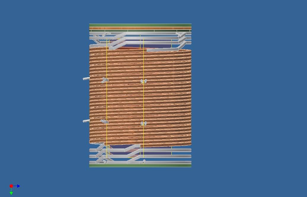
Coil
The US roots show as the coil cross-section has round copper tube. Most manufacturers now will use rectangular or “D-section” tube as this helps
Make furnaces run quieter
Enables easier coil compression, creating less vibration and longer lining life
No battens are shown, but a fully clamped coil is superior to one using battens, especially at the higher power densities used today
Note that the coil has upper cooling, power and lower cooling sections. The cooling sections are continuations of the power section so earth leakage is monitored on all sections. The cooling sections are also designed to prevent over-cooling of those sections, which would otherwise cause uneven lining cooling and cracking between sections.


Lid
Shown is a conventional lid, with no fume extraction or fume hood, which are almost mandatory today. The lid refractory needs to be lightweight to reduce mechanical forces on the lid operating mechanisms.
Without a lid, the furnace radiation losses, when using fully molten iron, would be ~280kW/sqm.
When using fume hoods, the refractory surface temperature can quickly change from 1450C (lid fully shut) to 50C (lid open, full air flow), so putting severe stress on the refractory.
Refractory Lining
The Allied website shows there is a wide array of lining refractories available. To the designer, these still tend to fall into the categories of alumina, silica and magnesite linings. Thermal data for each material is crucial for determining the optimum lining thickness from an efficiency point of view.
As illustrated on the graph below( X=melt/coil diameter, Y=efficiency/100),
thinner linings are electrically more efficient, but thermally less so, and vice versa for thicker linings. Note that the intersection point is the most efficient. (Green= thermal eff, red = electrical eff, brown = overall eff)
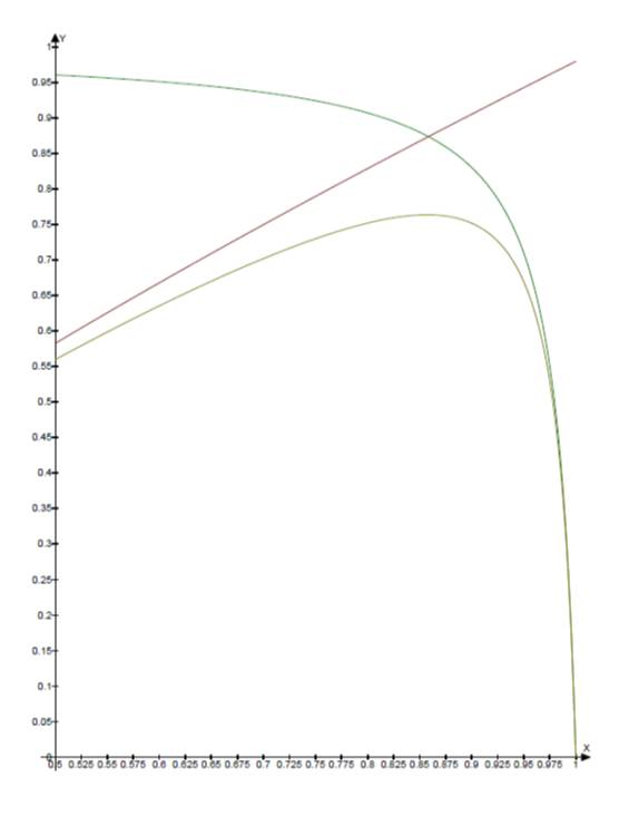

Refractory lining thickness design and efficiency of furnace
Some points to note from this
For non-ferrous metals (lower electrical efficiency), thinner linings may be better
Thicker linings, as often preferred by customers to increase lining life, makes the system less efficient, so using more energy. However, if the lining material is more thermally conductive (e.g. alumina vs silica) there may be some advantage to a thicker lining d/D ratios from 0.75 to 0.85 are generally optimal
So, the important thing to note from this is to be aware that changing refractory type may have other consequences.
The fettling and probe
One point noted on the Allied website is the success in patching the “elephant’s foot” at the bottom of the lining when melting iron. Care must be taken with this to patch the sidewalls only.
Any patch over the furnace bottom will cover the earth leakage probes, effectively disconnecting the earth leakage detection and making operation unsafe.
Also on the website is mention of earth leakage wires for Inductotherm (3mm, 304 stainless) and ABB (5mm, NiCr). If melting non-ferrous, NiCr is often preferable, regardless of furnace maker, as stainless may be reactive with the metal being melted (e.g. Aluminium).
The power operation parameters and the thickness of the lining
From an operating point of view, length of lining life is important. Measuring the lining regularly would show where areas are worn. The old rule was the lining should be replaced when it was worn 1/3 evenly, or ½ in any spot. However, with many operations 24/7, this measurement is not so easy to do, and replacement may be made based on a known tonnes/lining.
However, meter readings can also be used as an indicator of lining life.
After sintering, a fully molten furnace will have some voltage and frequency at a particular power.
As the lining wears, the voltage will reduce, and frequency increase for the same power level under fully molten conditions. The voltage will typically reduce to 90% of its sinter value, and the frequency increase to 105% when the lining is 1/3 worn. (Exact values depend on the actual furnace design.)
These meters can also be used as a guide to other lining conditions. If the lining is too thick, the voltage will be higher, and frequency will be lower for a given power. This could indicate buildup, or incorrect former placement. If both frequency and voltage read higher, it could mean a different alloy is being used (such as high chrome stainless), or a tank capacitor has failed.
Coil Grout
The coil grout helps make the coil a solid block, and is the last defense against metal penetrating the coil. Some grout features are must be tapered to allow for lining expansion/contraction, and for easier lining pushout should use high alumina for strength and temperature rating can be used inside AND outside. Outside use prevents stray scrap from being drawn into the coil and arcing.
Note that one feature of our coils are studs welded at regular intervals to the inside of the coil. The stud lengths are tapered to approximate the desired grout taper. That means that, when there is a metal penetration of the lining, the metal will pool against the grout and eventually touch one of these studs. That will bring up the earth leakage alarm well before the metal reaches the coil proper.
Coil grout maintenance during re-lining is critical to long lining/coil life.

Slip Plane
The slip plane against the coil grout is useful to smooth out any wrinkles that occur when the coil grout is patched. Some care needs to be used as follows too many layers, or using a thermally insulating material, may increase the overall lining thermal resistance, meaning that, while reducing thermal losses, the lining itself may sinter back too far, so reducing lining life .when melting zinc-coated steel scrap, several layers of mica, or Allied’s “Vapor Guard” should be used to trap the zinc vapour before it reaches the coil.
On non-ferrous melters, such as copper, using alumina linings, there is some advantage in usuing a thermally insulating slip-plane material to reduce the copper “freezing” against the lining, especially at the top of the furnace.
Structural Components/Bottom Castable
As shown in the coil cross-section, these can be coil supports under the coil, and the top blocks placed on top of the coil. Such items are always under compression. The sort of force can be estimated from a 6 tonne furnace.
Tie-bolt/rod 50 diameter, tightened to 100N-m, means Force ~ 100/.025 = 4000N = 400kg
With 10 bolts, total force ~4000kg
Coil width ~ 50mm. Coil diameter ~1200mm. So, compressed area ~ 0.2 sq m. That means the compression is ~20000kg/sq m (~28psi). This is not overly much to a continuous cast block, but, for precast shapes as shown in the cross-section, needs accuracy to prevent local overpressure. As coils deform over time, such support blocks do not line up as easily, meaning they are prone to damage. Once a support block is damaged, then the whole furnace integrity is compromised, leading to more vibrations and shorter lining life.
Xinyan prefers to use a coil sitting on the bottom castable so such a problem does not occur.
Which brings us to the bottom castable.
Top Castable
The top castable or blocks again used to be bricks. The castable is generally made in several blocks for ease of handling. These blocks ideally are pre-cast and dried to reduce moisture on during sinter. They are usually high alumina, and should have low shrinkage so they do not cause cracks in the lining, nor change pressure on the coil.
Conclusion
In case you missed the Xinyan plugs
Rectangular coil, properly compressed, for higher efficiency, quieter operation, and longer lining life
Coil grouted on outside as well to prevent rubbish getting on the coil
Coil with studs for earlier detection of metal penetration, and earth leakage on power and cooling sections
Lining thickness optimized for best efficiency
Lid castable and lower castables chosen to reduce thermal losses
Older furnaces used to have bottom bricks in two layers – a layer of light firebrick under a layer of dense firebrick. The aim was to make sure the bottom of the furnace did not get too hot.
These bricks have now been replaced by castable material, which is typically high alumina, and so has a higher thermal conductivity than the old brick system. This meant that replacing bricks with a castable often led to red furnace bottoms! So, care needs to be taken that the bottom castable is not only strong enough for the forces on the coil, but thermally insulating enough to reduce the thermal losses so the furnace bottom does not get too hot (< 200 C). That may involve adding thermal insulation under the castable, and often, on higher frequency furnaces, adding a copper plate to make sure stray magnetic fields do not cause direct heating. The simplest solution is design for a thicker bottom castable.