Furnace in energy conservation and emissions reduction facto
1、 Rectifier transformer
Guarantee transformer supplier know the load type of transformer, the load of medium power supply transformer is a rectifier load, which should kept the main efficiency shown on the transformer nameplate. Generally speaking, we use K coefficient to measure the loss caused by the transformer harmonics. The K coefficient of 6 pulses rectifier transformer is K-9, while K coefficient of 12 pulses rectifier transformer is K-4, The efficiency of rectifier transformer is entirely possible to reach 99% in common condition, Normally, we choose 98.5% as the minimum value.
2、 Incoming lines of the transformer
The energy loss, which is caused by connecting lines between secondaly side of transformer and medium power supply, is very small. When considering regular current density of bus bar and cable, the energy lose is 6/V% per meter. Here V is the voltage of incoming line of medium frequency power supply. For example, when the primary voltage of the transformer is 10kV, and the secondaly side is 575V, we had better plant transformer and power supply as closely as possible. Shorten distance between transformer and power supply at maximum degree contributes to reduce the energy loss on the side of power supply.
For example, the secondaly side voltage of transformer is 575V,and the distance is 20 meters, then there will be 0.2% energy loss.
3、 Medium frequency power supply
The main loss of the medium frequency power supply depends on the type and frequency of inverter.
The following is an energy loss comparision of main components when F<700Hz.
|
|
SCR |
IGBT |
|
|
Series |
Parallel |
Series |
Parallel |
|
DC Choke |
1.1% |
1.9% |
1.1% |
1.9% |
|
didt chokes |
0.9% |
0.45% |
0% |
0% |
|
Devices |
0.8% |
0.58% |
1.6% |
1.2% |
|
(Rel#) |
(2) |
(1) |
(4) |
(2) |
|
Total |
2.8% |
2.9% |
2.7% |
3.1% |
The comparision above shows us there is a little difference between main components.When device works at low frequency, the loss of IGBT is higher than SCR, when the same current is needed, the number of IGBT is more than SCR. But with frequency increasing, the rated capacity of SCR reduced. Normally IGBT has more advantages when the frequency is above 2kHz.
4、Resonance capacitor
Normally, we consider ~0.15W/100kVAr as the loss of resonance capacitor. Whether it is a series resonance or a parallel resonance circuit, the resonance capacitors are used for compensating power factor caused by coil lag. So for the energy loss, there is no much difference between the two kinds of circuits.
However, using capacitors with high capacity in practice has more advantages of energy-saving. It can reduce the dimension of cabinet, number of capacitors and cables connected capacitors and busbar, so lower energy loss can be achieved.
5、Output busbar
Considering the regular current density,typical energy loss can be calculated by the following datas ;
For water cooled busbur, the loss is 0.1% per meter.
For air cooling busbar, the loss is 0.065% per meter.
If only take the energy loss into consideration, it is very important to reduce the length of water cooled leads and the distance between inverter output and furnace, Air cooling busbar has higher efficiency, but it needs more busbars and more cooling spaces when device runs.Double number busbar can not reduce the general energy loss, The following illustration can show clearly.
Suppose the temperature of cooling water is below 40℃, The resistivity of busbar is 1.86u-ohm cm when temperature reaches 40℃.
Suppose the ambient temperature is 35℃,The resistivity of busbar is 2.16u-ohm cm whentemperature reaches 85℃.
When using one water cooled busbar, the energy loss is 1.86 x 1^2 = 1.86.
When using two air cooling busbar, the energy loss is 2.16*((1/3)^2 + (2/3)^2) = 1.20, because current-carrying capacity of the two busbars is not distributed as 50/50, but 33/67.
6、Water cooled leads
General speaking, the energy loss of water cooled leads is 0.23%/m.
The energy loss of water cooled leads is much higher than output busbar, so shorten the length of water cooled length as far as possible is very important. Increasing the number of water cooled leads is helpful to reduce the energy loss. However, normally too many water cooled leads is not practical when furnace is tilted.
7、Electric furnace
The electric furnace is the biggest part of energy loss, but energy saving can be achieved by the following means.
Using good, clean lining.
Organized the structure of lining well, improve the efficiency of efficiency.
Form good habit of covering the lid.
Maintain the lining well, avoid crosslink, when the lining is too thin, stop to use it.
7.1 Electrical loss
The electrical loss of induction coil depends on the shape of coil, resistivity and frequency of metal, when the proportion of effective coil’s diameter and height is 1:1,inside diameter of the melting bath is (0.75-0.8) of inside diameter of coil, and the device runs at 200-300Hz, the electrical loss of coil is :
Coil electrical loss: about 18%.
The loss of shunts and short-circuit ring:about 1.5%.
Loss in total:19.5%
Calculations above is based on the sectional area of coil copper tube is rectangle, coil duty ratio is more than 0.8, and the height of rectangle tube coil is higher 3% than circle tube coil.
7.2 Heat loss
Heat loss is mainly depends on heat conductivity coefficient of lining material, but for iron casting application case, we usually choose quartz sand lining.
Furnace with lid, and its power density is 500kW/ton, heat loss is in the range of 10.6% - 2.3% when the weight of melting iron is from 1ton to 25ton.
Furnace with lid, and its power density is 750kW/ton, heat loss is in the range of 7.1% - 1.5%
Furnace without lid, and its power density is 500kW/ton, heat loss is in the range of 24.2% - 6.9 % when the weight of melting iron is from 1ton to 25ton.
Furnace without lid, and its power density is 750kW/ton, heat loss is in the range of 16.1 % - 4.6 %
We can see clearly that design with high power density and lid can improve the efficiency by the comparison above,it has a abvious advantage when whole melting iron heating or holding.
7.3 Comprehensive consideration of electrical and heat loss
We can see heat and electrical loss of medium furnace has an interesting influence on total loss by comparison of the table below.
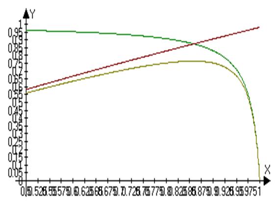
The curve below shows something about lining tamping, increasing the thickness of lining improves the life of lining, However, it also reduces the efficiency of electrical furnace. Reducing the thickness of lining to improve the efficiency of the furnace results in shorter life time of lining. Experience before told us that it is time to change lining when current thickness of lining is 2/3 of design thickness. For small furnace, inside diameter of combustion chamber is from 0.75 to 0.83 of coil’s can ensure the best efficiency range, For big furnace, the coefficient should be range from 0.8 to 0.87.
Other energy loss of auxiliary device
There are several sets of configured auxiliary system, including,
——cooling system
——hydraulic system
——dust-removal system
Water cooling system works continuously when electrical furnace is running. After the furnace is off, Cooling system won’t stop running until furnace cools down completely.
Normally for different system, there are different cooling system form, such as open-loop cooling system, closed-loop cooling system, evaporative cooling tower, dry cooling tower, water saving cooling system. While the most common form is closed-loop cooling tower system, which is consist of water pump, spray pump of cooling tower, fans of cooling tower. Since the flow rate is proportional to the power of medium frequency induction furnace, and water pump’s power is proportional to the rate of flow.we can think water pump’s power is proportional to medium frequency furnace’s.
Heat-sinking capability of cooling system is proportional to the power of furnace, so the power needed when cooling tower runs is also proportional to furnace’s power. Here is a relationship about power of water pump, cooling tower on and electrical furnace.
So in system with “one power supply and one furnace”, the energy loss rate is 1.2% of whole medium frequency induction furnace system.
The following are some means to reduce energy loss:
Ensure the temperature switch controlled by cooling tower fan works well,and the setting value is not too low.
Ensure outer circulating water is clean.
Ensure spray tube of cooling tower free,coil pipe of the cooling tower clean,to keep high cooling efficiency.
Ensure spray pump is turned on earlier and turned off later than cooling tower fan, avoid the coil pipe of cooling tower scaling.
Hydraulic system
The size of hydraulic pump of the hydraulic system has a direct relationship with the size of medium frequency furnace. The size of hydraulic pump is about three times of furnace’s ton to ensure two minutes’tilting time, For example, for 10 tons furnace, the power of the hydraulic pump is 30kW in hydraulic system.
Suppose the running time of hydraulic pump is 10 minutes per hour, the power density of the furnace is 500kW/ton, energy loss for the hydraulic system is 0.1% of the whole system, which is very small compared to system’s loss. But remember to turn off hydraulic system in time when it is not needed.
Furnace fume device
Since fume device has a demand for air volume, the fan power of fume device depends on the furnace’s tons, the type of furnace lid, and the melting material. For instance, the fan power of fume hood is twice of the fume ring’s. General speaking, fan’s power is proportional to the cube root of furnace’s tons.
Based on the calculation of fume ring,the energy loss of fume system is in a range like this:the energy loss of 1ton furnace fume system is 0.4% of the system. while for 25 ton furnace, the fume system is 0.14% of the whole melting system. To the melting system with one power supply and one furnace,we have not much energy saving work to do, but to multiple furnaces melting system and when the furnace doesn’t need a fume device, there should be a switching device.
